Support » Programming Orangutans and the 3pi Robot from the Arduino Environment »
2. ATmega168/328-Arduino Pin Mapping
- 2.a. Orangutan SV-xx8 and LV-168 Pin Mappings
- 2.b. Baby Orangutan B Pin Mappings
- 2.c. 3pi Robot Pin Mappings
In our standard Orangutan and 3pi documentation, we use the same convention that Atmel uses in its ATmega168/328 datasheet, referring to pins by their associated ports. For example, pin PD7 is pin 7 of port D. This convention is used because each port is controlled by its own AVR registers, and the bits of these registers correspond to individual pins.
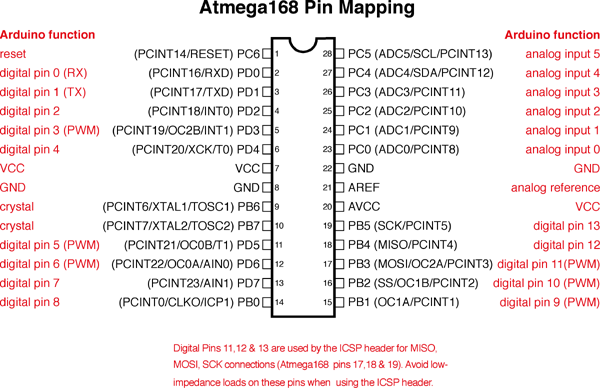
The Arduino insulates the user from this level of detail, referring to the I/O pins as digital pins 0 to 13 and analog inputs 0 to 7. Note that this terminology can be a bit misleading since analog inputs 0 to 5 can also be used as general purpose digital I/O pins (referred to as digital pins 14 to 19).
You can visit http://www.arduino.cc/en/Hacking/PinMapping168 to see exactly how the mega168/328 pins are mapped to Arduino pins. Note that this page shows a 28-pin DIP package chip while the Orangutans carry smaller 32-pin MLF packages that contain two additional dedicated analog inputs: ADC6 and ADC7. In the Arduino environment, these pins become arduino analog inputs 6 and 7, respectively. The following diagram comes from the page linked above:
 |


